Experimental
Commission the drivetrain
Canonical source: openamr-platform-hw/electrical/motor_control/motors-drivers.md
Applies to: the documented OpenAMRobot reference mobile base; verify repository revision before changing hardware or firmware.
Experimental project documentation
These instructions describe the current reference build and its measured behavior. Use physical safeguards, test with wheels clear of the floor, and revalidate after changing parts, wiring, firmware, battery chemistry, or geometry.
Last updated: 2026-06-17.
Overview
Two BLDC (brushless) motors, one per wheel, each driven by its own ZBLD driver. The Teensy sends low-current logic signals to the drivers; the drivers deliver the 24 V power to the motor phases.
- Motors: ZD Z4BLD60-24GN-30S ×2 — 3-phase BLDC, 24 V, 60 W, P=5 (5 pole pairs, on the nameplate), 3000 rpm motor + 1:25 spur gearbox (4GN 25K) → 120 rpm wheel, rated 3.8 A. U/V/W + Hall. (LEFT=M1, RIGHT=M2) See the sizing calculations.
- Drivers: ZBLD.C20-120L2R ×2 (24 V, 7.5 A, 120 W). Full specs + datasheets: components-bom.md. Red LED / fault blink codes: motor-driver-fault-codes.md.
- ⚠️ Pole pairs = 5 → verify the driver DIP SW4/SW5 are set to 5 pole pairs (read the silkscreen table on the driver). A wrong pole-pair setting throws off the driver's closed-loop speed scaling.
Manufacturer reference diagram
The driver's full terminal layout, DIP-switch table, and LED status codes, from the manufacturer:
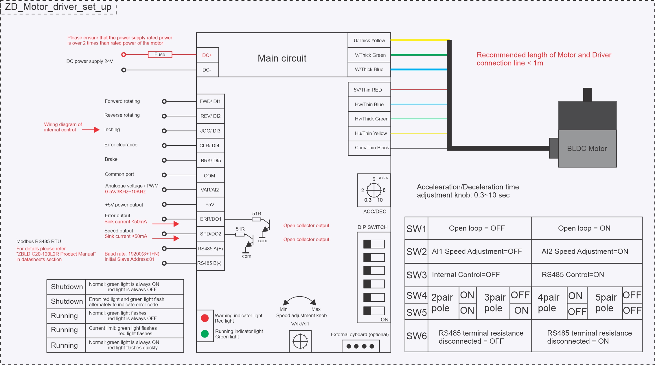
Source: ZD ZBLD.C20-120L2R product manual (manufacturer reference figure). This robot wires only a subset of these terminals and uses a specific DIP configuration — both are detailed below.
Communication (Teensy → driver)
The motor-control signal chain is shown below.
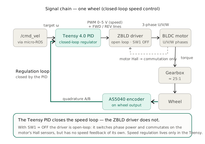
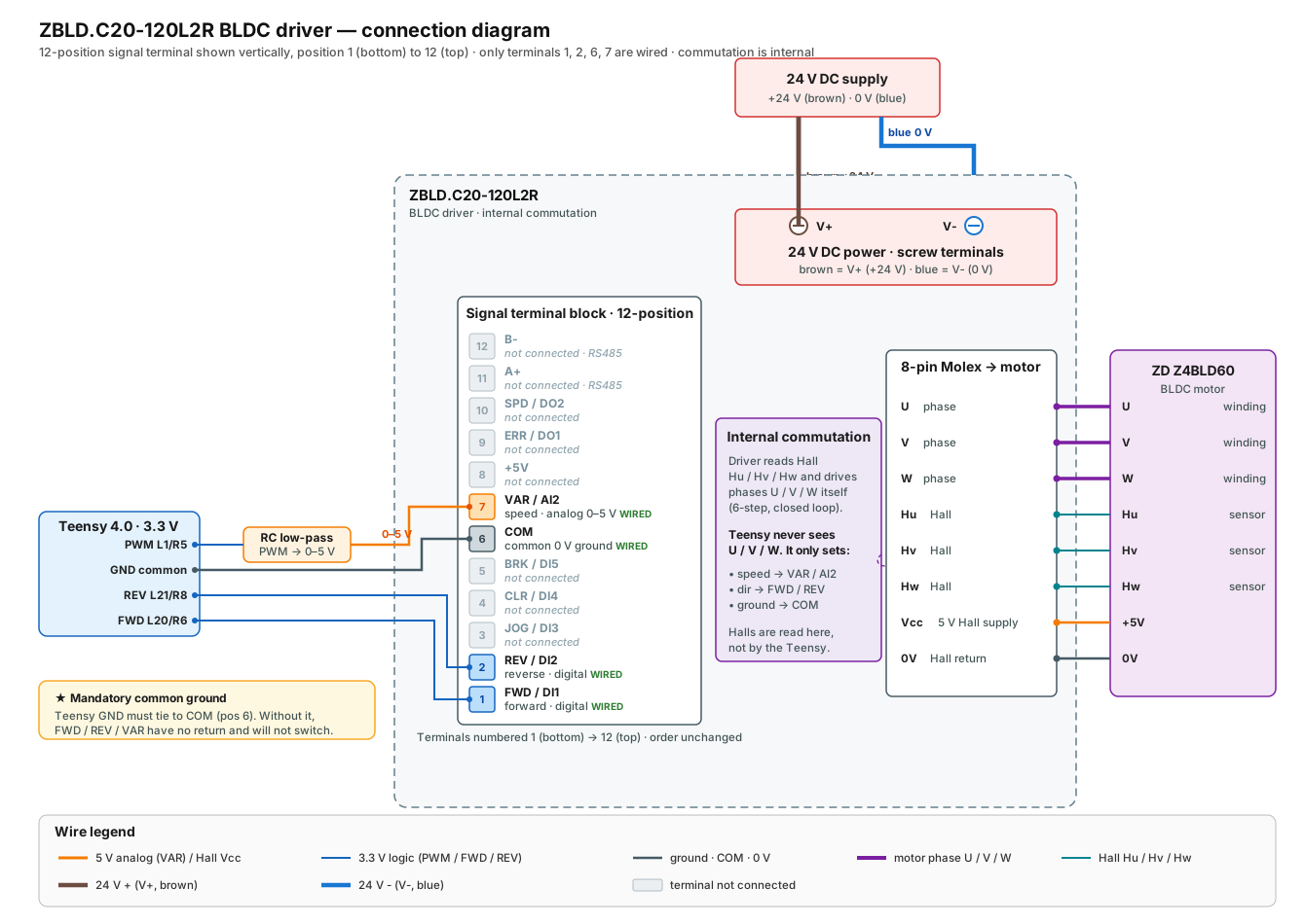
Per motor, 3 logic lines from the Teensy:
| Teensy signal | Driver input | Meaning | Left pin | Right pin |
|---|---|---|---|---|
| PWM | VAR / AI2 |
speed setpoint — Teensy PWM @ 3 kHz on this robot (driver capability: PWM 0–20 kHz, or analog 0–5 V) | 1 | 5 |
| IN_A | FWD / DI1 |
forward direction | 20 | 6 |
| IN_B | REV / DI2 |
reverse direction | 21 | 8 |
| GND | COM |
common ground (mandatory) | GND | GND |
- Power side:
DC+ / DC− = 24 V(with a fuse). Motor side: phases U/V/W + Hall. - ⚠️ The driver
COMmust be tied to the Teensy GND, otherwise signals/encoders are noisy.
Of the driver's twelve control terminals, this robot wires only four — the connections are shown below:
Driver configuration — DIP switches (SW1–SW6)
Both drivers must be set identically. Functions read from the driver silkscreen (2026-06-19):
| Switch | Function | What it does | Was (pre 06-19) | Now (applied 06-19) |
|---|---|---|---|---|
| SW1 | open / closed loop (开环/闭环) |
ON = driver regulates speed itself from the Halls; OFF = driver is just a power stage (Teensy regulates) | ON | OFF |
| SW2 | speed source (AI1/AI2) |
OFF = internal VAR knob; ON = external 0–5 V on VAR/AI2 (our Teensy PWM) |
ON | ON |
| SW3 | secondary (direction/internal) | no effect here (direction is driven by FWD/REV pins) | OFF | OFF |
| SW4 / SW5 | motor pole pairs (极对数) |
tells the driver the pole-pair count (2/3/4/5) to convert Hall freq → RPM. Only used in closed loop | OFF/OFF (= 2 pp ⚠️) | ON/ON (= 5 pp) |
| SW6 | RS485 termination (485 终端电阻) |
bus end resistor; not used (no RS485) | OFF | OFF |
🔶 Pole-pair mismatch found & corrected (2026-06-19): the motor is P=5 (5 pole pairs, on the nameplate) but SW4/SW5 were OFF/OFF (= 2 pole pairs). Now set to ON/ON (= 5 pp). (Only matters in closed loop; harmless but correct in the current open-loop config.)
Which controller is best — driver vs Teensy PID?
The Teensy PID is the better controller for this robot and should be the authoritative one:
- it reads the AS5040 encoder (1024 cnt/rev) → fine resolution, and measures the wheel speed
(post-gearbox) — the variable we actually care about (motion + odometry);
- it is fully tunable (K_P/K_I/K_D, already tuned to ±2 %), and feeds ROS /odom.
- the driver's loop measures the motor shaft (pre-gearbox) with coarse Hall sensors, is opaque
(only VAR/ACC pots), and needs correct pole pairs.
→ Run the driver open-loop (SW1=OFF) so the Teensy is the sole regulator (removes the double-loop that worsens snaking; makes pole pairs irrelevant). Plan B if low-speed cogging appears: go back to closed loop (SW1=ON) with SW4/SW5=ON/ON (5 pp) for a proper cascade (fast driver inner loop + Teensy outer). The only edge the driver loop has: at low wheel speed the motor shaft still spins ~30× faster → richer Hall signal → potentially smoother very-low-speed than the 50 Hz Teensy loop.
Config applied 2026-06-19 (both drivers): SW1 OFF · SW2 ON · SW3 OFF · SW4 ON · SW5 ON · SW6 OFF.
(Was SW1 ON, SW2 ON, rest OFF.) Validated over 3 motor runs — see
the openamr-platform-sw troubleshooting doc (docs/troubleshooting/diagnostics.md in that repo).
⚠️ VAR pot is inert in this config: with SW2=ON the speed comes from AI2 (the PWM), not the VAR/AI1 pot, so turning VAR does not balance the wheels (confirmed: no change across runs). The residual ~9 % open-loop L/R asymmetry (right faster) is corrected by the Teensy PID (→ ~0.2 % in closed loop).
Driver configuration — TWO trim pots (CRITICAL)
Each driver has two potentiometers. They must match between LEFT and RIGHT (calibrate the right to the left, the known-good reference).
⚠️ Read this alongside the config state. The VAR gain effect below (and the "runaway" root cause) applies when VAR is in the speed path — i.e. the original config (VAR/AI1 selected, or an AI2 gain that scales the PWM). In the current config (SW1=OFF open loop, SW2=ON → AI2) the speed comes from the PWM on AI2, so the VAR pot is inert for balancing (see the note above) — the values below are the setting to leave it at, not a live balancing knob. ACC/DEC still ramps in either config.
| Pot | Location | Function | Correct setting | Symptom if wrong (when VAR is in the speed path) |
|---|---|---|---|---|
| VAR | top | speed / gain (PWM → speed) | ~3.5/10, same both sides | too high → wheel runs ~8× too fast → runaway |
| ACC/DEC | near the DIP switches | acceleration/deceleration ramp | 4/10, same both sides | =0 → no smoothing → jerks/oscillation in closed loop |
See the full story in the openamr-platform-sw troubleshooting doc (docs/troubleshooting/diagnostics.md in that repo).
Low-speed behaviour — measured velocity floors (2026-07-02)
Closed-loop sweep on the ground / under load (/cmd_vel with the PID + dither, as in docking),
real velocity read on /odom/unfiltered:
| Axis | Stall | Judder | Reliable floor | Clean |
|---|---|---|---|---|
| Linear | ≤ 0.02 m/s | 0.03 (min 0, std 0.018) | 0.04 m/s (min 0.020) | 0.05 m/s (std 0.004); 0.06–0.10 perfect |
| Angular | ≤ 0.08 rad/s | 0.10–0.12 (min 0, high std) | 0.15 rad/s (min 0.093) | 0.20–0.30 perfect |
✅ The motor is WELL-SIZED (over-sized on torque). Above the floors the real/commanded ratio is ~1.0 → no torque shortfall. The floors are stick-slip (static friction) + coarse Hall commutation at low RPM (an operating-point limit, not a sizing one). Reference: the Z4BLD60-24GN-30S + 1:25 gearbox gives a mechanical no-load max of ~1.26 m/s (software-capped to ~0.71 m/s) and ~3.48 N·m/wheel (specs in components-bom.md, derivation in the sizing calculations).
Consequence: keep commanded velocities above the floors. Docking applies this (drive taper floored
at 0.05 m/s, scan rotation 0.17 rad/s, a min_turn_omega of 0.15 rad/s with a small deadband so
sub-floor yaw corrections are snapped up or zeroed rather than stalling). Judder on each start-from-standstill
is the static-friction breakaway; a taper (or the driver ACC/DEC ramp) mitigates it.
Good to know / gotchas
- The original fault ("right wheel runs away, robot doesn't go straight") was 100 % driver tuning, in the original config where VAR was in the speed path: the right VAR pot was at max (10) and its ACC/DEC pot at 0. After matching both pots to the left, the right wheel tracked correctly. (Separately, during open-loop balancing on 2026-06-19, raising the right VAR made the right wheel speed up to match a faster left — same knob, opposite direction, because it was a different starting point.)
- ⚠️ In the current config (SW2=ON, AI2 source) VAR no longer balances the wheels — the residual L/R asymmetry is handled entirely by the Teensy PID (the right channel needs slightly more PWM for the same speed; the PID compensates → ~0.2 % in closed loop). Do not chase balance with the VAR pot here.
- Test the motors safely with the open-loop mode (
/debug/openloop) which bypasses the PID — useful to compare the two channels at identical PWM. See theopenamr-platform-fwdebug-telemetry doc (docs/architecture/debug-telemetry.md). - Always: wheels off the ground, 24 V on, a hand on the 24 V cut-off for the first tests.
Engineering handoff
- Record the repository commit, hardware revision, supply voltage, and test configuration with every result.
- Stop if observed wiring, component labels, geometry, or topic behavior differs from this page; resolve the discrepancy in the owning repository first.
- Report documentation or implementation defects through the repository issue tracker.