Experimental
Calibrate encoder ripple
Canonical source: openamr-platform-fw/docs/architecture/encoder-calibration.md
Applies to: the documented OpenAMRobot reference mobile base; verify repository revision before changing hardware or firmware.
Experimental project documentation
These instructions describe the current reference build and its measured behavior. Use physical safeguards, test with wheels clear of the floor, and revalidate after changing parts, wiring, firmware, battery chemistry, or geometry.
Applies to the Teensy 4.0 linorobot2_overlay firmware.
The left wheel showed a slow low-speed "oscillation" (a ~1 s, ±6 rpm limit cycle) that barely responded to PID gains. It was not a control-loop problem: the left AS5040 magnet is off-centre, so the measured rpm carries a geometric ripple that the PID was chasing. This page documents the ripple, the deployed runtime correction table + per-boot phase re-align (the working fix), and why a static/compiled table can't work and the velocity filter was rejected.
The ripple (measured)
An open-loop constant-speed sweep, binning measured rpm by wheel angle (counts mod CPR), showed:
- LEFT wheel: a 2-cycle-per-revolution, ~40 % peak-to-peak error (≈ 0.85 → 1.22), identical at 120 / 180 / 250 PWM → locked to wheel angle, not time = a mechanical encoder defect (off-centre / tilted AS5040 magnet), not a real speed oscillation.
- RIGHT wheel: only ~±4 % (well aligned).
No PID gain can remove an artefact that is in the measurement itself.
Runtime correction table (/debug/enc_cal)
The firmware holds a per-wheel correction table and divides the measured rpm by the table entry at the current wheel angle:
ENC_CAL_NBINS = 36bins,ENC_CAL_CPR = 1024. Two tables:LEFT_CAL[36],RIGHT_CAL[36].- Applied in
calib_rpm()tocurrent_rpm1/2before the PID and odometry — instant, no averaging, no lag. A table entry ≤ 0.05 is ignored (guard against divide-by-tiny). - Loaded at runtime via
/debug/enc_cal(std_msgs/Float32MultiArray, 72 floats = 36 left then 36 right). Until a table is received, both tables default to 1.0 = passthrough (raw rpm), so an un-calibrated boot behaves exactly like no correction.
Why the table is loaded at runtime, not compiled in
The encoder is read incrementally: counts start from 0 at every Teensy boot, at whatever
position the wheel happens to be in. So counts mod 1024 is an angle relative to the boot
position, not an absolute wheel angle. Every reflash reboots the Teensy and shifts the encoder
zero by a random (and different left/right) angle.
A compiled-in table would therefore be applied at the wrong phase after every flash. A compiled table was tried and failed to converge (it even produced an anti-phase result that doubled the ripple). The working approach loads the table at runtime so its phase matches the current boot's encoder zero.
Calibration workflow (host-side)
The calibration workflow is shown below.
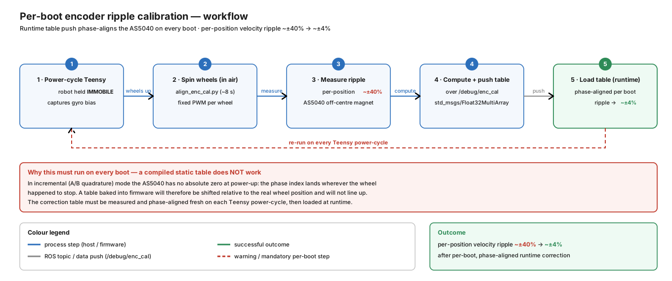
The shape of the ripple is fixed (it is the magnet geometry); only its phase moves per boot. So the shape is captured once as a reference, and each boot only re-aligns the phase:
- A reference table (fixed shape) lives in the host tooling
(
tools/encoder-calibration/encoder_ref_table.json). The alignment scripts are host-side (they run on the Pi / a dev PC, not on the Teensy) and are vendored in this repo undertools/encoder-calibration/. - After every Teensy power-cycle, a short alignment run (~6–8 s) spins the wheels, measures
the raw per-angle ripple, correlates it sub-bin (~1°) against the reference to find the current
phase, rolls the reference to that phase, and publishes the 72-float table on
/debug/enc_cal. Run it from the host, wheels off the ground, with the micro-ROS agent up and 24 V power on:(Seecd tools/encoder-calibration && source /opt/ros/jazzy/setup.bash \ && export RMW_IMPLEMENTATION=rmw_cyclonedds_cpp ROS_DOMAIN_ID=0 \ && python3 align_enc_cal.py --arm 250tools/encoder-calibration/README.mdfor the full-recalibration workflow used when the magnet is physically disturbed.) - The table lives in Teensy RAM, so it must be re-sent after a power-cycle — a ROS restart on the host does not require re-alignment, but a Teensy reboot does.
⚠️ Alignment gotcha: the alignment routine must flatten the table to 1.0 (passthrough) before measuring. If it measures with a table already loaded, it reads the residual of the loaded table, computes the wrong phase, and produces an anti-phase table that doubles the ripple (~71 %, worse than raw). Symptom: the post-check shows a larger ripple than the raw baseline.
The ±40 % (LEFT) / ±4 % (RIGHT) figures above are the raw, un-calibrated ripple — what you
see when no table is loaded (unity passthrough) or before align_enc_cal has run this boot. After
alignment the residual is boot-dependent (the per-boot phase lock is never identical): a clean
full recalibration lands under ±5 % on the LEFT, while a fast per-boot alignment can sit higher
(up to ~±11 %) depending on how well the phase locked that boot. Either way it is flat, instant,
far below the ±40 % raw, and it survives a reboot once re-aligned.
The deployed fix (and the alternatives that were rejected)
The in-use, working ripple fix is the hot-loaded correction table (calib_rpm) + a per-boot
phase re-align (align_enc_cal.py, ~8 s). That is what brings LEFT from ±40 % to ±4 % and
survives a reboot once re-aligned. It is a per-boot ritual — the phase must be re-aligned every
power-cycle, and the flatten-before-measure gotcha is easy to hit — but it is the deployed solution,
not a stopgap for something else.
What does not work, and what was rejected:
- A static / compiled-in table fails. The encoder is incremental, so
counts mod CPRis an angle relative to the boot position; every reboot shifts the encoder zero by a random (and different left/right) angle, so a fixed table is applied at the wrong phase (see the section above). Only a table that is re-aligned at runtime each boot can work. - A half-revolution angular velocity filter (average over 512 counts) cancels the ripple cleanly but adds ~0.6 s of lag — considered and rejected for closed-loop control. The deployed ripple fix is not this velocity filter.
- Do not conflate the ripple fix with the firmware's separate small-window (12-count) velocity estimator: that is only a low-speed quantization-noise filter (see control loop), it does not remove the per-angle ripple — the align-table does.
The only durable hardware fix is better encoder mounting (a centred/untilted AS5040 magnet), which removes the geometric ripple at the source. Until then, the runtime align-table + per-boot re-alignment is the working solution.
See control loop for where calib_rpm sits in the loop, and
debug telemetry
for the wire format.
Engineering handoff
- Record the repository commit, hardware revision, supply voltage, and test configuration with every result.
- Stop if observed wiring, component labels, geometry, or topic behavior differs from this page; resolve the discrepancy in the owning repository first.
- Report documentation or implementation defects through the repository issue tracker.