Experimental
Firmware control architecture
Canonical source: openamr-platform-fw/docs/architecture/control-loop.md
Applies to: the documented OpenAMRobot reference mobile base; verify repository revision before changing hardware or firmware.
Experimental project documentation
These instructions describe the current reference build and its measured behavior. Use physical safeguards, test with wheels clear of the floor, and revalidate after changing parts, wiring, firmware, battery chemistry, or geometry.
Applies to the Teensy 4.0 linorobot2_overlay firmware.
The firmware runs a fixed-rate control loop that turns /cmd_vel into per-wheel PWM,
publishes wheel odometry, and streams debug telemetry. This document describes the loop,
the velocity controller, and the compiled configuration for this robot.
The 50 Hz loop (src/firmware.ino)
A micro-ROS timer fires every 20 ms (50 Hz) → controlCallback → moveBase() then
publishData().
/cmd_vel (Twist)
   │
   ▼
kinematics.getRPM(vx, vy, wz) ─► target rpm per wheel  (motor1 = LEFT, motor2 = RIGHT)
   │                                   ▲
   │  encoder + velocity estimator ────┘ measured rpm (ripple-corrected)
   ▼
feedforward(target) + pid.compute(target, measured) ─► PWM ─► motor.spin() ─► driver ─► wheel
   │
   ▼
kinematics.getVelocities(rpm1..4) ─► measured vx, wz
   │
   ▼
odometry.update() ─► /odom/unfiltered
moveBase() selects one of three exclusive paths each tick, checked in this order:
- Open-loop diagnostic — active only when a bounded
/debug/openloopcommand is fresh (< 300 ms). Bypasses the PID and drives a fixed PWM. See debug telemetry. - Command watchdog stop — if no
/cmd_velarrived within 200 ms, the loop does a deterministic full stop (brake + PID reset). See motion safety. - Closed-loop control — the normal path (below).
Odometry is integrated on every tick regardless of which path ran.
Velocity controller (closed-loop path)
The closed-loop control path is shown in the block diagram below.
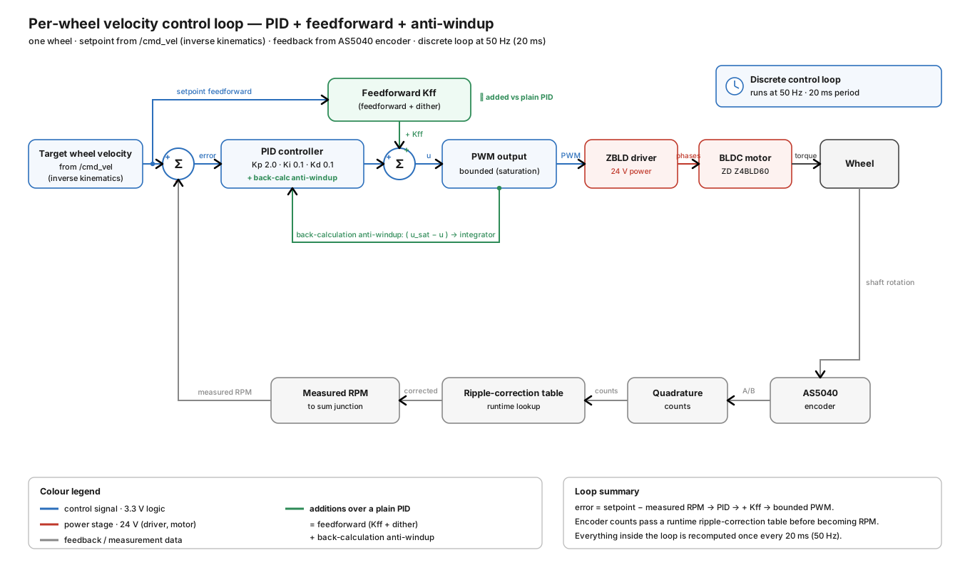
Per wheel, the commanded PWM is a feedforward + PID sum:
- Feedforward supplies the bulk of the holding PWM directly:
pwm_ff = kff · target_rpm ± ff_offset(theff_offsetstiction term is added in the direction of motion). Defaults:KFF_DEFAULT = 7.87PWM/rpm,FF_OFFSET_DEFAULT = 21PWM. Because the feedforward already knows the PWM needed for a given speed, the integral barely works, so the closed-loop response has the same shape at every speed (no speed-dependent windup/overshoot). - PID (
lib/pid/pid.cpp) only trims the residual error. One PID per wheel, output clamped to[PWM_MIN, PWM_MAX]. The integral uses back-calculation anti-windup: on saturation the excess is subtracted straight back out of the integral (integral -= (pid − limit) / K_I), soK_I · integralonly ever supplies what is actually achievable. This bleeds the windup out rather than a static clamp or a conditional freeze — a long saturated rise no longer overshoots. Upstream linorobot2 had an unbounded integral that "catapulted" on saturation. - Right-wheel balance:
motor2PWM is scaled bymotor2_gain(defaultMOTOR2_GAIN = 1.000). The feedforward + integral now carry the drivetrain asymmetry, so no per-wheel gain scaling is needed; the scalar is kept live-tunable for convenience.
Differential-drive rule: both wheels share a single
K_P/K_I/K_Dset (identical closed-loop dynamics → the robot tracks straight). Established left/right asymmetry is compensated with the scalarmotor2_gain, not with per-wheel gains (per-wheel gains make the robot veer on start).
Low-speed handling
At docking speeds the raw encoder rate is too coarse and static friction dominates. Two mechanisms address this:
- Small-window velocity estimator — instead of counts-per-fixed-20 ms (only ~1 count per
sample below ~5 rpm → ±70 % quantization noise that the PID would chase), the firmware measures
the time to accumulate a fixed 12-count displacement (
Δcounts / Δt, Δt at microsecond precision). Look-back is capped at 200 ms. Lag is ~20–30 ms at nav speed (negligible). - Anti-stiction dither — below
DITHER_BELOW_RPM = 13rpm, a PWM of±dither_amp(DITHER_DEFAULT = 92) is flipped every control tick (≈25 Hz square wave, net average 0). It keeps the wheels micro-moving so static friction never grabs, converting the 0→9 rpm stick-slip limit cycle into smooth slow motion down to ~0.06 m/s. Above 13 rpm it is disabled.
See encoder calibration for the ripple correction applied to the measured rpm, and motion safety for the measured velocity floors.
Kinematics & odometry
LINO_BASE = DIFFERENTIAL_DRIVE;motor1 = LEFT,motor2 = RIGHT(motors 3/4 unused).- For pure forward motion both wheels get the same target rpm. Per-wheel wheel velocity:
LR_WHEELS_DISTANCE(0.46 m) is the track (wheel separation), not the wheel diameter (0.2 m). max_rpm = (MOTOR_POWER_MAX_VOLTAGE / MOTOR_OPERATING_VOLTAGE) · MOTOR_MAX_RPM · MAX_RPM_RATIO. With real 24 V power both voltages must be 24 or the RPM ceiling is halved.- Odometry is integrated from the measured wheel velocities and published on
/odom/unfiltered(the host EKF fuses it with the IMU). An abnormal first/largedt(> 0.5 s) is rejected so the first sample doesn't jump.
Compiled configuration (config/lino_base_config.h)
Values for this robot (differ from upstream linorobot2 defaults):
#define |
Value | Notes |
|---|---|---|
LINO_BASE |
DIFFERENTIAL_DRIVE |
2 driven wheels |
USE_GENERIC_2_IN_MOTOR_DRIVER |
— | PWM + 2 direction pins (INA/INB) |
USE_MPU9250_IMU |
— | chip is actually an MPU-6500 (see bringup) |
K_P / K_I / K_D |
2.0 / 0.1 / 0.1 |
K_I low because the feedforward does the holding (2026-06-29) |
MOTOR2_GAIN |
1.000 |
right-wheel PWM scale; FF + integral carry the asymmetry |
MOTOR_MAX_RPM |
80 |
|
MAX_RPM_RATIO |
0.85 |
usable ceiling = 68 rpm |
MOTOR_OPERATING_VOLTAGE / MOTOR_POWER_MAX_VOLTAGE |
24 / 24 |
must match real supply |
COUNTS_PER_REV1..4 |
1024 |
encoder CPR |
WHEEL_DIAMETER |
0.2 |
m |
LR_WHEELS_DISTANCE |
0.46 |
m, track (measured 2026-06-19) |
PWM_BITS / PWM_FREQUENCY |
10 / 3000 |
PWM_MAX = 1023, PWM_MIN = −1023 |
MOTOR1_ENCODER_INV / MOTOR2_ENCODER_INV |
true / false |
encoder sign |
MOTOR1_INV / MOTOR2_INV |
false / true |
motor direction sign |
MOTOR1_PWM / IN_A / IN_B |
1 / 20 / 21 |
LEFT (pin 1 is PWM-capable on Teensy 4.x; 21 is not) |
MOTOR2_PWM / IN_A / IN_B |
5 / 6 / 8 |
RIGHT |
MOTOR1_ENCODER_A / B |
14 / 15 |
LEFT quadrature |
MOTOR2_ENCODER_A / B |
11 / 12 |
RIGHT quadrature |
BAUDRATE |
115200 |
must match the micro-ROS agent |
The following live in src/firmware.ino (compiled defaults, live-tunable via /debug/tune):
| Symbol | Default | Meaning |
|---|---|---|
KFF_DEFAULT |
7.87 |
feedforward gain (PWM/rpm) |
FF_OFFSET_DEFAULT |
21 |
feedforward stiction offset (PWM) |
DITHER_DEFAULT |
92 |
anti-stiction dither amplitude (PWM) |
DITHER_BELOW_RPM |
13 |
dither active only below this target rpm |
⚠️ The build env
teensy40usesconfig/lino_base_config.h, not anydev_config.h. Editlino_base_config.hfor gain/pin/geometry changes.
Tuning history (context)
The gains reached the current values in two stages:
- 2026-06-18 step-response tune (no feedforward): raised the original slow gains to
K_P 0.6 / K_I 0.35 / K_D 0.15; K_I was the dominant fix (killed a ~−26 % steady-state error). Adding K_D did not help — it amplifies the quantized rpm noise, and the right-wheel overshoot was dominated by driver dynamics + measurement quantization (the measurement noise floor), not by gains. - 2026-06-29 feedforward re-architecture (current): with the feedforward carrying the holding
PWM, K_I was lowered to
0.1and K_P raised to2.0; the response became speed-independent andMOTOR2_GAINreturned to1.000. The low-speed velocity estimator and anti-stiction dither were added at the same time.
The left wheel's low-speed "oscillation" was ultimately traced to an encoder measurement artefact, not the gains — see encoder calibration.
Engineering handoff
- Record the repository commit, hardware revision, supply voltage, and test configuration with every result.
- Stop if observed wiring, component labels, geometry, or topic behavior differs from this page; resolve the discrepancy in the owning repository first.
- Report documentation or implementation defects through the repository issue tracker.